Fun with sobel - Neon Effect - Thick Edge Detection

Questions and postings pertaining to the usage of ImageMagick regardless of the interface. This includes the command-line utilities, as well as the C and C++ APIs. Usage questions are like "How do I use ImageMagick to create drop shadows?".
HugoRune
Posts: 90
Joined: 2009-03-11T02:45:12-07:00
Authentication code: 8675309

Re: Fun with sobel - Neon Effect - Thick Edge Detection

Post by HugoRune »

Some tests with whiteboards.
cleaning was done with

Code: Select all

for %a in (*-hough.*) do convert "%a" ^
    ( +clone  -scale 12.5% -blur 0x30 -resize 800% ) ^
    +swap -compose divide -composite ^
    ( -clone 0 -contrast-stretch 2%,50% -threshold 60% ^
        -blur 4x2 -threshold 99% ^
        -blur 4x2 ^
    ) -compose screen -composite ^
    -contrast-stretch 0% "%~na-clean.png"
[/size]
Image
ImageImageImageImage
As expected, some confusion about the double edges, might be solvable with edge orientation information

Image
ImageImageImageImage
I am surprised that actually worked. My sobel script needs contrast between object and background, and it's all yellow. There is much less edge noise than in a normal printed page though, so hough still finds the correct edges (except top)

Image
ImageImage
Failure due to missing upper edge. At least the missing lower left corrner and distorted vertical edges would not have been a problem in this case.
User avatar
fmw42
Posts: 25562
Joined: 2007-07-02T17:14:51-07:00
Authentication code: 1152
Location: Sunnyvale, California, USA

Re: Fun with sobel - Neon Effect - Thick Edge Detection

Post by fmw42 »

your cleaning results are pretty good. just a little spotty on the first one, but I had trouble too

edge direction may help in separating the double border from the wood on the first one.

you have a lot of lines and color dots drawn on each example. is that manually or from your Hough transform. if the latter, when and if you are willing to post, I would be very interested in the complexity of how you solved that and then for the corners and how you throw out false intersections. How much comes from openCV? So your solution relies upon other tools to do a lot of the work in that regard?

But nice work.

I will have to experiment with your cleaning technique and make some comparisons with mine.
HugoRune
Posts: 90
Joined: 2009-03-11T02:45:12-07:00
Authentication code: 8675309

Re: Fun with sobel - Neon Effect - Thick Edge Detection

Post by HugoRune »

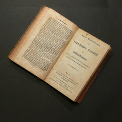
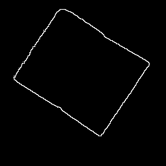
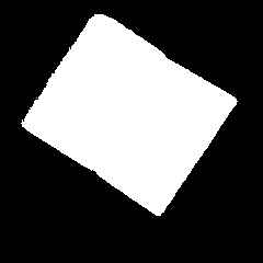
The colored lines are the debugging output from my script.

It is about 400 lines, could be shorter, and uses openCV for canny edge detect, hough transform and graphic display.

It uses imagemagick, but currently by calling sobelseries.bat and convert.exe through the shell. I want to use the imagemagick python interface instead, but do not know when I get around to that.

I did not implement my own hough transform, but I probably should, because the opencv one is lousy. No working Non-Maximum-Supression, and no way to access the accumulator values for each line, just their order. No simple way to use orientation information for hough transform either.

The algorithm for selecting the best quadrangle was created by me, and is a bit hacked, but it seems to work. Basically I sort the lines by strength, take the strongest detected line, and keep adding lines that satisfy all quadrangle criteria
(like, all quadrangle sides must be longer than X, all corners must be >30°, must be convex)

There are currently no sanity checks for command line paramters, and in case of any error it simply crashes.
Only rudimentary comments, and the code is a mess.
The quadrangle detection and the preprocessing could be improoved a lot.
Aspect ratio recognition has not been iintegrated, and currently it simply maps all rectangles to 1682x2378 pixels (DIN A4)

But it worked for all the photographed pages I threw at it.

I want to make some of these changes and then make an official release, but I do not know how soon I get around to that.
Might be a while, since the original reason I made this script was the thousands of pages I photographed, and I still have to read them all.

Here is a little preview, feedback welcome:

Code: Select all

#!/usr/bin/python
# This program is free software: you can redistribute it and/or modify
# it under the terms of the GNU General Public License as published by
# the Free Software Foundation, either version 3 of the License, or
# (at your option) any later version.

# This program is distributed in the hope that it will be useful,
# but WITHOUT ANY WARRANTY; without even the implied warranty of
# MERCHANTABILITY or FITNESS FOR A PARTICULAR PURPOSE.  See the
# GNU General Public License for more details.

# You should have received a copy of the GNU General Public License
# along with this program.  If not, see <http://www.gnu.org/licenses/>.
#
################################################################
#
# This is a standalone program.  
# it requires 
# - python 2.6+ ( 2.5 or 2.4 works probably too)
# - openCV with PythonInterface installed
# - imagemgagick with convert somewhere in the path (only required for batch processing)
# - sobelseries.bat in the same directory or somewhere in the path (only required for batch processing)
# 
################################################################
#
# USAGE:
#
# 1) DISPLAY
# houghlines.py IMAGEFILE
#      use hough transform to detect lines in the image, 
#      identify most prominent perspective-distorted rectangle, 
#      display results on screen, wait for keypress
#
# 2) BATCH PROCESSING
# houghlines.py INFILE OUTFILE
#     use sobelseries.bat to filter nonrelevant edges, (NEEDS SOBELSERIES.BAT)
#     identify most prominent rectangle,
#     correct perspective in INFILE, write results to OUTFILE  (NEEDS IMAGEMAGICK)

import sys
import subprocess
import os
from math import sin,cos,sqrt,degrees,radians
from opencv.cv import *
from opencv.highgui import *

# Find point (x,y) where two parameterized lines intersect 
# lines are given i the hough form (rho,theta)
# returrns None for parallel lines
def intersectLines2(r1, t1, r2, t2) :
	ct1=cos(t1)
	st1=sin(t1)
	ct2=cos(t2)
	st2=sin(t2)
	d=ct1*st2-st1*ct2
	if abs(d)>0.000001 :   
		x = ((st2*r1-st1*r2)/d)
		y = ((-ct2*r1+ct1*r2)/d)
		return (x,y)
	else: #lines are parallel
		return None

def intersectLines(line1,line2):
	return intersectLines2(line1[0],line1[1],line2[0],line2[1])

		
#returns true if the point is within the given axis-aligned rectangle. all points are tuples
def pointInRect(point,rect):
	topLeft,bottomRight = rect
	if point[0]>=topLeft[0] and point[1]>=topLeft[1] and point[0]<=bottomRight[0] and point[1]<=bottomRight[1]:
		return True
	else: return False


def angledist(theta1,theta2):
	return abs( (theta1 + CV_PI/2 - theta2) % CV_PI - CV_PI/2 )
	# print degrees(angledist(radians(0),radians(0))),"=0"
	# print degrees(angledist(radians(0),radians(90))),"=90"
	# print degrees(angledist(radians(0),radians(180))),"=0"
	# print degrees(angledist(radians(0),radians(270))),"=90"
	# print degrees(angledist(radians(0),radians(360))),"=0"
	# print degrees(angledist(radians(0),radians(179))),"=1"
	# print degrees(angledist(radians(0),radians(181))),"=1"

	# print degrees(angledist(radians(180),radians(0))),"=0"
	# print degrees(angledist(radians(180),radians(90))),"=90"
	# print degrees(angledist(radians(180),radians(180))),"=0"
	# print degrees(angledist(radians(180),radians(270))),"=90"
	# print degrees(angledist(radians(180),radians(360))),"=0"
	# print degrees(angledist(radians(180),radians(-1))),"=1"
	# print degrees(angledist(radians(180),radians(1))),"=1"

	# print degrees(angledist(radians(-180),radians(0))),"=0"
	# print degrees(angledist(radians(-180),radians(90))),"=90"
	# print degrees(angledist(radians(-180),radians(180))),"=0"
	# print degrees(angledist(radians(-180),radians(270))),"=90"
	# print degrees(angledist(radians(-180),radians(360))),"=0"
	# print degrees(angledist(radians(-180),radians(-1))),"=1"
	# print degrees(angledist(radians(-180),radians(1))),"=1"


def angle_deg(line1,line2):
	return  angledist(line1[1] ,line2[1]) / CV_PI * 180


#this does not work in some cases
def rhodist(rho1,rho2):
	#return abs( abs(rho1)-abs(rho2) )
	return abs( rho1-rho2 )
	
def pointdist(p1,p2):
	return sqrt((p1[0]-p2[0])**2 + (p1[1]-p2[1])**2)
	

# not used anymore
def sortQuadranglePoints2(pointlist):
	"""
	  a-------b
	  |       |
	  |       |
	  c-------d
	"""
	# sort 4 points so that
	# a = from the leftmost points, the topmost
	# b = from the topmost points, the leftmost
	# d = from the rightmost points the topmost
	# c = last point
	
	points = pointlist[0:4]
	points.sort()
	a = points.pop(0)
	points.sort(key=lambda p: (p[1],p[0]))
	b = points.pop(0)
	points.sort(key=lambda p: (-p[0],p[1]))
	d = points.pop(0)
	c = points.pop(0)
	print " %1.4f,%1.4f 0,0 %1.4f,%1.4f 1000,0 %1.4f,%1.4f 1000,1000 %1.4f,%1.4f 0,1000 " % (a[0],a[1],b[0],b[1],d[0],d[1],c[0],c[1])
	return a,b,c,d

def sortQuadranglePoints(pointlist):
	"""
	  a-------b
	  |       |
	  |       |
	  c-------d
	"""
	# sort 4 points so that
	# a = topleftmost point
	# b = from the remaining points, the toprightmost point
	# d = from the remaining points, the bottomrightmost point
	# c = last point
	
	points = list(pointlist[0:4])
	points.sort(key=lambda p: (p[0]+p[1],p[0]))
	a = points.pop(0)
	points.sort(key=lambda p: (-p[0]+p[1],p[1]))
	b = points.pop(0)
	points.sort(key=lambda p: (-p[0]-p[1],-p[0]))
	d = points.pop(0)
	c = points.pop(0)
	return a,b,c,d


# picks a rectangel from an ordered list of points
# algorithm:
# - start with the first line
# - keep adding lines that satisfy rectangle criteria
# returns the 4 corner points or None
def pickQuadrangle(houghlines,width,height):
	"""
	  a-------b  b-------a
	  |       |  |       |
	  |       |  |       |
	  c-------d  d-------c
	"""
	# at the end the corner points will be ordered abdc clockwise or counterclockwise
	a,b,c,d = None,None,None,None # corner points
	vanish1,vanish2 = None,None # vanishing points
	ab,ac,bd,cd = None,None,None,None # lines
	
	mindist  =min (width,height) / 6 # minimum lengt of one side
	bigrect  =(-width/4,-height/4),(width*1.25,height*1.25) # the 4 corners have to be in this area
	smallrect=(width/4,height/4),(width*0.75,height*0.75) # the 2 vanishing points have to be outside this area

	lines = houghlines[:] 
	
	
	for dummy in 0, :
		#pick the strongest line as ab
		if len(lines)>0: 
			ab = lines.pop(0)
			print "found ab", ab
		else: 
			break

		for line in lines:
			# pick line ~perpendicular to first line (angle + pointinrect):
			ac = line
			if angle_deg (ab , ac) < 45 : continue

			a = intersectLines (ab , ac)
			if not a or not pointInRect (a , bigrect) : continue

			print "found ac", ac
			break
		else: 
			ac = None; a = None
			break
		lines.remove(ac)

		for line in lines:
			# pick line ~perpendicular to either line 
			bd = line
			if angle_deg (ac , bd) > 30 : (ab,ac) = (ac,ab)
			if angle_deg (ab , bd) < 30 : continue
			
			
			b = intersectLines (ab , bd)
			if not b or not pointInRect (b , bigrect) : continue
			if pointdist (b , a) < mindist : continue
			
			vanish1 = intersectLines (ac , bd)
			# vanishing point  should be None or far away
			if vanish1 and pointInRect (vanish1 , smallrect) : continue

			print "found bd", bd
			break
		else: 
			bd = None; b = None; vanish1 = None
			break
		lines.remove(bd)

		for line in lines:
			# pick line perpendicular to ac AND bd:
			cd = line

			if angle_deg (ac , cd) < 30 : continue
			if angle_deg (bd , cd) < 30 : continue
			
			c = intersectLines (cd , ac)
			if not c or not pointInRect (c , bigrect) : continue
			if pointdist (c , a) < mindist : continue
			if pointdist (c , b) < mindist : continue

			d = intersectLines (cd , bd)
			if not d or not pointInRect (d , bigrect) : continue
			if pointdist (d , a) < mindist : continue
			if pointdist (d , b) < mindist : continue
			if pointdist (d , c) < mindist : continue

			vanish2 = intersectLines (cd , ab) 
			# vanishing point  should be None or far away
			if vanish2 and pointInRect( vanish2 , smallrect) : continue

			print "found cd", cd
			break
		else: 
			cd=None; c=None; d=None; vanish2=None
			break
		lines.remove(cd)
	else: return (a,b,c,d)
	
	print "NOT ENOUGH LINES"
	return None
	

#convert s  a openCv data structure into a proper python list of tupples
def convertCVList(linesCV):
	lines=[]
	for line in linesCV: lines.append((float(line[0]),float(line[1])))
	return lines

# check if a line is similar to some other lines
def distinctLine(line,goodlines,min_rho_dist,min_theta_dist):
	rho2,theta2 = line
	for rho1,theta1 in goodlines:
		if rhodist(rho1,rho2)<min_rho_dist and angledist(theta1,theta2)<min_theta_dist:
			return False
	return True


# from an ordered list of lines , remove all lines that are "very similar" to an earlier line.
# makeshift Non-Maximum-Supression
def filterLines(lines,min_rho_dist,min_theta_dist):
	goodlines=[]
	for line in lines: 
		if distinctLine(line,goodlines,min_rho_dist,min_theta_dist): goodlines.append(line)

	return goodlines


if __name__ == "__main__":
	filename = "testhough.jpg"
	if len(sys.argv)>1:
		filename = sys.argv[1]
		
	if len(sys.argv)>2:
		cmdline = "sobelseries.bat",sys.argv[1],"tmpsobel.png"
		try: os.remove("tmpsobel.png")
		except Exception: pass
		print "> ",cmdline
		subprocess.check_call(cmdline,shell=True)
		filename = "tmpsobel.png"

	src=cvLoadImage(filename, 0);
	if not src:
		print "Error opening image %s" % filename
		sys.exit(-1)

	dst = cvCreateImage( cvGetSize(src), 8, 1 );
	color_dst = cvCreateImage( cvGetSize(src), 8, 3 );
	color_dst_small = cvCreateImage( cvSize(min(src.width,1000),min(src.height,900)), 8, 3 );
	storage = cvCreateMemStorage(0);
	
	#cvCanny( src, dst, 20, 50, 3 );
	cvCanny( src, dst, 50, 200, 3 );
	#cvCanny( src, dst, 100, 1000, 3 );
	#dst=src

	#lines = cvHoughLines2( dst, storage, CV_HOUGH_STANDARD, 1, CV_PI/180, 100, 0, 0 );
	#lines = cvHoughLines2( dst, storage, CV_HOUGH_MULTI_SCALE, 10, CV_PI/180, 100, 10, 11 );
	linesCV = cvHoughLines2( dst, storage, CV_HOUGH_STANDARD, 1, CV_PI/180 , 50, 0, 0 );
	lines=convertCVList(linesCV)

	min_rho_dist=100
	min_theta_dist=radians(10)

	
	goodlines=filterLines(lines,min_rho_dist,min_theta_dist)
	quadranglePoints = pickQuadrangle(lines,src.width,src.height)

	if quadranglePoints: 
		a,b,c,d = sortQuadranglePoints(quadranglePoints)
		print a,b,c,d
		if pointdist(a,b) + pointdist(c,d) > pointdist(a,c) + pointdist(b,d):
			#landscape
			perspectivestring =  "%1.2f,%1.2f 1682,0 %1.2f,%1.2f 1682,2378 %1.2f,%1.2f 0,0 %1.2f,%1.2f 0,2378" % (a[0],a[1],b[0],b[1],c[0],c[1],d[0],d[1]) 
		else:
			perspectivestring =  "%1.2f,%1.2f 0,0 %1.2f,%1.2f 1682,0 %1.2f,%1.2f 0,2378 %1.2f,%1.2f 1682,2378" % (a[0],a[1],b[0],b[1],c[0],c[1],d[0],d[1]) 
		print perspectivestring
	if len(sys.argv)>2:
			cmdline = "convert",sys.argv[1],"-set option:distort:viewport 1682x2378","-distort perspective \"" + perspectivestring + "\"",sys.argv[2]
			print "> ", cmdline
			subprocess.check_call( " ".join(cmdline),shell=True)

	
	if len(sys.argv)<>3:
		cvCvtColor( dst, color_dst, CV_GRAY2BGR );

		for i in range(min(len(goodlines), 100)-1, -1, -1):
			line = goodlines[i]
			#print line[0], round(line[1]/CV_PI*180)
					
			rho = line[0];
			theta = line[1];
			pt1 = CvPoint();
			pt2 = CvPoint();
			a = cos(theta);
			b = sin(theta);
			x0 = a*rho 
			y0 = b*rho
			pt1.x = cvRound(x0 + 5000*(-b));
			pt1.y = cvRound(y0 + 5000*(a));
			pt2.x = cvRound(x0 - 5000*(-b));
			pt2.y = cvRound(y0 - 5000*(a));
			linecolor=CV_RGB(255-min(255*i/10,200),0,255*i/10)
			cvLine( color_dst, pt1, pt2, linecolor, 4, 8 );


		def makeCvPoint(point):
			cvpoint = CvPoint()
			cvpoint.x = cvRound(point[0])
			cvpoint.y = cvRound(point[1])
			return cvpoint

		if quadranglePoints: 

			a,b,c,d = sortQuadranglePoints(quadranglePoints)
			cvCircle (color_dst, makeCvPoint(a), 20, CV_RGB(255,0,0), -1)
			cvCircle (color_dst, makeCvPoint(b), 20, CV_RGB(255,255,0), -1)
			cvCircle (color_dst, makeCvPoint(c), 20, CV_RGB(0,255,0), -1)
			cvCircle (color_dst, makeCvPoint(d), 20, CV_RGB(0,0,255), -1)

			for x1,y1 in quadranglePoints:
				for x2,y2 in quadranglePoints:
					if x1!=x2 or y1!=y2:
						pt1 = CvPoint()
						pt2 = CvPoint()
						pt1.x=cvRound(x1)
						pt1.y=cvRound(y1)
						pt2.x=cvRound(x2)
						pt2.y=cvRound(y2)
						cvLine( color_dst, pt1, pt2, CV_RGB(0,255,255), 2, 8 );

			
		else:
			#lines = cvHoughLines2( dst, storage, CV_HOUGH_PROBABILISTIC, 1, CV_PI/180, 50, 40, 5 );
			lines = cvHoughLines2( dst, storage, CV_HOUGH_PROBABILISTIC, 1, CV_PI/180, 10, 50, 1000 );
			cvCvtColor( dst, color_dst, CV_GRAY2BGR );
			for i in range(min(lines.total, 10)-1, -1, -1):
				line = lines[i]
				linecolor=CV_RGB(255-min(255*i/10,200),0,255*i/10)
				cvLine( color_dst, line[0], line[1], linecolor, 5, 8 );

		cvNamedWindow( "Source", 1 );
		cvShowImage( "Source", src );

		cvResize ( color_dst, color_dst_small)
		cvNamedWindow( "Hough", 1 );
		cvShowImage( "Hough", color_dst_small );

		cvWaitKey(0);
User avatar
fmw42
Posts: 25562
Joined: 2007-07-02T17:14:51-07:00
Authentication code: 1152
Location: Sunnyvale, California, USA

Re: Fun with sobel - Neon Effect - Thick Edge Detection

Post by fmw42 »

That is a lot of hard work! I think you have done a great job getting what you have as this is not an easy problem.

But the fact that it uses openCV and perhaps Python is going to limit its use with IM users. But don't let this comment deter you. Use what you need to get the job done.

I was just hoping you had developed something that could be folded into IM as IM needs a good Hough Transform and other feature detection tools. But that may be beyond the scope of IM as it is really an image processor not feature detector.
I did not implement my own hough transform, but I probably should, because the opencv one is lousy. No working Non-Maximum-Supression, and no way to access the accumulator values for each line, just their order. No simple way to use orientation information for hough transform either.
Too bad as that is usually important.
HugoRune
Posts: 90
Joined: 2009-03-11T02:45:12-07:00
Authentication code: 8675309

Re: Fun with sobel - Neon Effect - Thick Edge Detection

Post by HugoRune »

But the fact that it uses openCV and perhaps Python is going to limit its use with IM users. But don't let this comment deter you. Use what you need to get the job done.
Well the idea was that when this program is released, the imagemagick and openCV libraries can be bundled with it, so the user only needs python installed.
With py2exe, not even that.

I was just hoping you had developed something that could be folded into IM as IM needs a good Hough Transform and other feature detection tools. But that may be beyond the scope of IM as it is really an image processor not feature detector.
Folding hough transform into IM hadn't occcured to me, I do not think that would be a good match. The final output you usually want is a list of lines, so nothing that can be easily manipulated with imagemagick. Not to mention the extended hough transforms where the hough space has more than 2 dimensions.
Nevertheless, I think a representation of basic hough line space might be doable with the fx operator, if it somehow allows referencing pixel values in the output image for reading.
someting like -fx "output.p{func1(u),func2(u)} = output.p{func1(u),func2(u)} + u"
where func1 und func2 are the equation "i cos(theta) + j sin(theta) = rho" solved for rho and theta, and u is an edge image with all edge pixels=1 and all other pixels=0
Not sure if the fx operator can do this
User avatar
fmw42
Posts: 25562
Joined: 2007-07-02T17:14:51-07:00
Authentication code: 1152
Location: Sunnyvale, California, USA

Re: Fun with sobel - Neon Effect - Thick Edge Detection

Post by fmw42 »

Folding hough transform into IM hadn't occcured to me, I do not think that would be a good match. The final output you usually want is a list of lines, so nothing that can be easily manipulated with imagemagick. Not to mention the extended hough transforms where the hough space has more than 2 dimensions.
Nevertheless, I think a representation of basic hough line space might be doable with the fx operator, if it somehow allows referencing pixel values in the output image for reading.
someting like -fx "output.p{func1(u),func2(u)} = output.p{func1(u),func2(u)} + u"
where func1 und func2 are the equation "i cos(theta) + j sin(theta) = rho" solved for rho and theta, and u is an edge image with all edge pixels=1 and all other pixels=0
Not sure if the fx operator can do this
Right, that was why I did not think IM was necessarily appropriate. What you really want out of the Hough is the definition of the lines as rho, theta pairs. But this does not give the line lengths. Lines are infinite or at least as long as necessary until they hit the edges of the image. In your case all you really just want are the intersections which you can get from "infinite" lines.

But what you get from an image is the gradient direction at each pixel. You can prune that with thresholding on the basis or gradient magnitude and even threshold the directions (perhaps as few as 8 ). Then you have to transform each direction for a given location to rho, theta and accumulate the pixels that have the same rho,theta. I suspect that one could do the gradient direction at x,y to rho,theta on an image. But the accumulator is the hard part within IM. Then you need to sort to get the highest accumulated values from the image. Then redraw the lines or find intersections. The rho,theta transform is just a means to an end and has little significance on its own.

I believe that Magick has implemented something a little similar using the radon transform to deskew an image. See http://en.wikipedia.org/wiki/Radon_transform. It is basically doing a similar kind of transformation to find directions of certain features in an image and reorient the image. Works for small rotations. See -deskew

So I suppose something like the Hough transform could be implemented. But then one still has to process the image to get the strong edges and their rho,thetas.

I have not had time to really look into this much even to do the rho,theta transform from the edge gradient directions. But am glad there are others who have an interest.
User avatar
fmw42
Posts: 25562
Joined: 2007-07-02T17:14:51-07:00
Authentication code: 1152
Location: Sunnyvale, California, USA

Re: Fun with sobel - Neon Effect - Thick Edge Detection

Post by fmw42 »

HugoRune
Posts: 90
Joined: 2009-03-11T02:45:12-07:00
Authentication code: 8675309

Re: Fun with sobel - Neon Effect - Thick Edge Detection

Post by HugoRune »

I have been thinking about doing a hough transform with the tools already provided by imagemagick, and it seems relatively straightforward.

All that is missing is a way to simulate the accumulator array.

This is just a random idea, but is there some way to do a 2d histogram in imagemagick?
I have seen your method of generating a 1d histogram for a single channel image:
convert zelda3.jpg -colorspace gray histogram:- | convert - -scale 256x1! zelda3g_hist.png
I there a way to extend this to a 2d histogram for a 2 channels?

For example, given the red/green channel of an image, can I create a 2d histogram image with
  • - 0-255 red values on the x axis
    - 0-255 green values on the y axis
    - the brightness of a pixel at x0,y0 determined by how often the color RGB(x0,y0,0) appears in the image
Such a 2d histogram could be used as an accumulator. With that and the fx operator, I think i could do a hough transform in one imagemagick command.
(of course, this migth fall under the category "just because you can does not mean you should")

EDIT: looking over this, I am actually not so sure anymore if it would work, I have to think about it again)
User avatar
fmw42
Posts: 25562
Joined: 2007-07-02T17:14:51-07:00
Authentication code: 1152
Location: Sunnyvale, California, USA

Re: Fun with sobel - Neon Effect - Thick Edge Detection

Post by fmw42 »

If you decide to push forward, with regard to 2D plots, see my scripts, scatter and scatterchannels. They are scattergrams. Don't know if this helps or not.
HugoRune
Posts: 90
Joined: 2009-03-11T02:45:12-07:00
Authentication code: 8675309

Re: Fun with sobel - Neon Effect - Thick Edge Detection

Post by HugoRune »

Well, the idea was this:

- Generate an image with the theta values of all edge pixels (the orientation of the gradient)
- Generate an image with the rho values of all edge pixels (The shortest distance to the origin of a line throught that pixel with orientation theta)
- create a 2d histogram: count how often each possible (rho,theta) value pair occcurs, and plot this with rho on one axis, theta on the other axis, brightness=number of occurences.

This should be equivalent to the oriented hough transform described in the paper by Zhang and He. The classic hough transform would require a lot more effort to compute this way (repeat the whole process N times, for all possible theta values, then add the resulting 2d plots).

In theory it should work, but using the process shown below I did not get any good results, and the whole thing seems extremely impractical and inefficient to me anyway.

Code: Select all

convert rectrot2.png  -resize 50x50! -colorspace gray ^
    ( -clone 0 -bias 50% -convolve "-0.125,0,0.125,  -0.25,0,0.25,  -0.125,0,0.125" ) ^
    ( -clone 0 -bias 50% -convolve "-0.125,-0.25,-0.125,  0,0,0,  0.125,0.25,0.125" ) ^
    -delete 0 ^
    -fx "uu=(u-0.5)*2;vv=(v-0.5)*2; hypot(uu,vv)>0.05 ? atan2(vv,uu) /pi/2+0.5 : 0"  -write THETA.png ^
    -fx "uu=(u-0.5)*pi*2; u>0 ? ((i/w)*cos(uu) + (j/h)*sin(uu)) /sqrt(2)/2+0.5 : 0" RHO.png

scatter THETA.png RHO.png HOUGH.png
input ------------------------------ THETA --------------------------- RHO
Image Image Image

Image

There are 4 peaks which might respond to the right lines, but it is hard to tell with all that noise. The binary nature of the scatter script makes this difficult, since it is impossible to tell how many counts each pixel represents, but the high calulation time limits the useability of this approach anyway.
User avatar
fmw42
Posts: 25562
Joined: 2007-07-02T17:14:51-07:00
Authentication code: 1152
Location: Sunnyvale, California, USA

Re: Fun with sobel - Neon Effect - Thick Edge Detection

Post by fmw42 »

This should be equivalent to the oriented hough transform described in the paper by Zhang and He. The classic hough transform would require a lot more effort to compute this way (repeat the whole process N times, for all possible theta values, then add the resulting 2d plots).
I agree and that was my first thought also

Does it help to quantize your theta values to the 8 primary compass directions? Also to threshold the magnitude to binary form partially to eliminate low priority edges (probably here it is not an issue as your image is not 'noisy'), but to make the edge strengths equal. This could help speed up processing the 2D histogram if you throw out zero magnitude edges (black pixels) or conversely just use edges with mag=1 (white pixels)
The binary nature of the scatter script makes this difficult
Yes, that is why I was not sure it would help other than give you an idea about how to produce a 2D histogram. But it needs extending so that it is grayscale and not binary.

So that was why I had hoped that the radon transform within -deskew might be immediately useable without too much effort. But it looks like it needs significant alteration and I have not yet replied to Magick with any pseudocode, but I have found several pieces of code and pseudocode to send him. However, he is always very busy and I don't expect it needs escalation to the top of his queue.
HugoRune
Posts: 90
Joined: 2009-03-11T02:45:12-07:00
Authentication code: 8675309

Re: Fun with sobel - Neon Effect - Thick Edge Detection

Post by HugoRune »

Some more experiments. I went back to python since I do not see a way to make the previous attempt work at acceptable speed and quality.

My conclusion is that the oriented hough transform is indeed much better suited than the classical for this particular problem.

Still not sure if this could or should be integrated with imagemagick. Seems like there are too many possible modifications for command line switches

original image:
Image

oriented hough transform
Image
This is simply using the orientation estimated from sobel. Very good results, much better peaks than the classical hough transform, less noise. Much faster to calculate too.
Only a few seconds for a medium-sized image, even in python.

classical hough transform
Image
Very long calculation time with my unoptimized python implementation.
As expected, the borders are lost amid the many edges from the text.
That is why I needed the solbelseries script from the first post in this thread to filter all small structures.

A modification I tried:
Image
A sort of combination of the two previous algorithms
Like the classical hough transfrom, I loop trough all possible theta values from -180° to +180°
But here I only add +1 to the accumulator bin when theta is within +-10° of the measured orientation. All other bins get -1

Seems very effective for certain noisy images. The peaks are also a bit sharper than with the oriented hough transform. As slow as the classical hough transform though.


Code: Select all

#!/usr/bin/python
# This program is free software: you can redistribute it and/or modify
# it under the terms of the GNU General Public License as published by
# the Free Software Foundation, either version 3 of the License, or
# (at your option) any later version.

# This program is distributed in the hope that it will be useful,
# but WITHOUT ANY WARRANTY; without even the implied warranty of
# MERCHANTABILITY or FITNESS FOR A PARTICULAR PURPOSE.  See the
# GNU General Public License for more details.

# You should have received a copy of the GNU General Public License
# along with this program.  If not, see <http://www.gnu.org/licenses/>.
#
################################################################
#
# This is a standalone program.  
# it requires 
# - python 2.6+ ( 2.5 or 2.4 works probably too)
# - openCV with PythonInterface installed
# 
################################################################
#
# USAGE: hough2.py SOURCEFILE [OUTFILE]
#

import sys
from math import sin,cos,sqrt,degrees,radians,atan2,hypot,pi
from opencv.cv import *
from opencv.highgui import *


# ORIENTED HOUGH TRANSFORM
def orientedHoughTransform(edges,sobelX,sobelY,accumulator):
	maxtheta = pi
	maxrho = hypot(edges.width, edges.height)
	maxacc = -1000000
	for x in range(0,edges.width):
		for y in range(0,edges.height):
			#print x,y, edges.width,edges.height
			if edges[y,x]>0:
				theta = atan2(sobelY[y,x],sobelX[y,x])
				rho = x*cos(theta) + y*sin(theta)
				t=int(round  ((theta/maxtheta/2  +0.5) * (accumulator.width-1) ))
				r=int(round  ((rho  /maxrho  /2  +0.5) * (accumulator.height-1)))
				acc=accumulator[r,t]
				acc+=1
				accumulator[r,t]=acc
				if acc>maxacc: maxacc=acc
				#print theta,sobelY[y,x],sobelX[y,x]
	cvConvertScale(accumulator,accumulator,100000/maxacc)

# ORIENTED HOUGH TRANSFORM WITH MODIFICATIONS
def orientedHoughTransform2(edges,sobelX,sobelY,accumulator):
	maxtheta = pi
	maxrho = hypot(edges.width, edges.height)
	maxacc = -1000000
	for x in range(0,edges.width):
		for y in range(0,edges.height):
			#print x,y, edges.width,edges.height
			if edges[y,x]>0:
				theta2 = atan2(sobelY[y,x],sobelX[y,x])
				for ii in range(-180,179):
					theta= radians(ii)
					rho = x*cos(theta) + y*sin(theta)
					t=int(  ((theta/maxtheta/2  +0.5) * (accumulator.width-1) ))
					r=int(  ((rho  /maxrho  /2  +0.5) * (accumulator.height-1)))

					acc=accumulator[r,t]
					if abs(theta-theta2)<radians(10): acc+=1
					else: acc-=1
					accumulator[r,t]=acc
					if acc>maxacc: maxacc=acc
				#print theta,sobelY[y,x],sobelX[y,x]
	print maxacc
	cvConvertScale(accumulator,accumulator,32767/maxacc)

				
if __name__ == "__main__":
	if len(sys.argv)>1:
		srcfile = sys.argv[1]
		
	srcImg=cvLoadImage(srcfile, 0);
	if not srcImg:
		print "Error opening image %s" % srcfile
		sys.exit(-1)
		
	edgeImg = cvCreateImage( cvGetSize(srcImg), 8, 1 );
	cvCanny( srcImg, edgeImg, 200, 100, 3 );

	sobelXImg = cvCreateImage( cvGetSize(srcImg), IPL_DEPTH_16S, 1 );
	cvSobel( srcImg, sobelXImg, 1, 0, 3 );

	sobelYImg = cvCreateImage( cvGetSize(srcImg), IPL_DEPTH_16S, 1 );
	cvSobel( srcImg, sobelYImg, 0, 1, 3 );

	accumulatorImg = cvCreateImage( cvSize(360,360), IPL_DEPTH_16S, 1 );
	cvZero( accumulatorImg );
	
	orientedHoughTransform(edgeImg, sobelXImg, sobelYImg, accumulatorImg)
	
	if len(sys.argv)>2:
		outfile = sys.argv[2]
		cvSaveImage(outfile,accumulatorImg)
	else:
		cvNamedWindow( "hough", 1 );
		cvShowImage( "hough", accumulatorImg );
		cvWaitKey(0);
		cvShowImage( "hough", edgeImg );
		cvWaitKey(0);
		# cvShowImage( "hough", sobelYImg );
		# cvWaitKey(0);

User avatar
fmw42
Posts: 25562
Joined: 2007-07-02T17:14:51-07:00
Authentication code: 1152
Location: Sunnyvale, California, USA

Re: Fun with sobel - Neon Effect - Thick Edge Detection

Post by fmw42 »

very nice work.

why 5 (not 4) bright spots? Is that due to the open pages on the left side of the book?

I wonder if something like this could be done with AWK (Anthony?)


Just for curiosity and comparison, I tried the ImageJ radon transform on the original and an edge image (both cropped to square dimensions required by the radon plugin)

image:
Image

radon:
Image

simple edge:
convert pic4nb.png -monochrome -median 2 -edge 1 pic4nb_mono_med2_edge1.png
Image

radon from edge image:
Image
HugoRune
Posts: 90
Joined: 2009-03-11T02:45:12-07:00
Authentication code: 8675309

Re: Fun with sobel - Neon Effect - Thick Edge Detection

Post by HugoRune »

fmw42 wrote:why 5 (not 4) bright spots? Is that due to the open pages on the left side of the book?
Not sure actually, it might be the middle of the book, or one of the other lines. I still have to finish the code that finds the local maxima in hough space and converts them back into lines.

I did not do any noise filtering on this image, just a canny filter with a low threshold to detect all edges. I wanted to see how it can deal with noisy images.
Image (the original image was resized before uploading)Image
I wonder if something like this could be done with AWK (Anthony?)
I never worked with AWK, but it seems like a bad match. Why AWK?
Just for curiosity and comparison, I tried the ImageJ radon transform on the original and an edge image (both cropped to square dimensions required by the radon plugin)
I never figured out what the advantages and disadvantages of the radon or the hough transform are for this sort of problem. Are there fundamental differences of the results (for the classical cases)?
Hough seems to be faster to calculate, if I only loop over the edges. and easier to thinker with. But that might be because the integrals confuse me.
simple edge:
convert pic4nb.png -monochrome -median 2 -edge 1 pic4nb_mono_med2_edge1.png
Image
interestingly, the oriented hough transform does not work at all if it only has this sort of edge image as input.
To calculate precise gradient orientation, The sobel results of the original images are needed
If I run sobel over this edge image, the gradient varies to much to give any meaningful result.
User avatar
fmw42
Posts: 25562
Joined: 2007-07-02T17:14:51-07:00
Authentication code: 1152
Location: Sunnyvale, California, USA

Re: Fun with sobel - Neon Effect - Thick Edge Detection

Post by fmw42 »

I never worked with AWK, but it seems like a bad match. Why AWK?
Just learning a bit of it and finding that for what it can do, it can do it so much faster than bash scripting with while or for loops.
I never figured out what the advantages and disadvantages of the radon or the hough transform are for this sort of problem. Are there fundamental differences of the results (for the classical cases)?
Hough seems to be faster to calculate, if I only loop over the edges. and easier to thinker with. But that might be because the integrals confuse me.
Not totally sure either. Seemed to be a bit less noise sensitive from what i have read. Also I knew that Magick had implemented some version of it and thought it might be something that could be extracted for direct use in IM easily (but not the case).

I made the examles, 1) knowing that you had not done much to reduce noise, 2) knowing that my edge result is different and not directly comparable to what you are doing, 3) it was available from ImageJ, and 4) just for curiosity to see the differences. Just learning more myself about both.
interestingly, the oriented hough transform does not work at all if it only has this sort of edge image as input.
To calculate precise gradient orientation, The sobel results of the original images are needed
If I run sobel over this edge image, the gradient varies to much to give any meaningful result.
I would not necessarily expect it to work as you are doing and edge extraction on an edge image. Perhaps better to try from the binary image I made before extracting the edge. Here it is:

Image
Post Reply